


2 3 4 5 core PVC insulation PVC sheath 0.61kv power cable-IEC60502 - 1 Power Cable
CU/PVC/PVC (2 Cores - 5 Cores)
PVC Insulated, PVC Sheathed Cable
Application
These power cable for fixed installations such as distribution networks or industrial installations.
Such as Plant engineering; Industrial machinery; Heating and air-conditioning systems; Power stations; Stage applications etc.
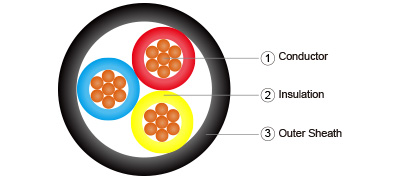
Construction
Conductor: Plain annealed copper, class 1 solid or class 2 stranded as per IEC 60228.
Flexible class 5 or tinned conductor could be offer upon request.
Insulation: Polyviny chloride (PVC) compound as per IEC 60502-1.
Insulation Colour:
| Number of Cores | Color Code to IEC 60502-1 | Color Code to BS 5467 |
| 2 | Red, Black | Brown, Blue |
| 3 | Red, Yellow and Blue | Brown, Black and Grey |
| 4 | Red, Yellow, Blue and Black | Blue, Brown, Black and Grey |
| 5 | Red, Yellow, Blue, Black and Green / Yellow |
Green / Yellow, Blue, Brown, Black and Grey |
Assembly: Cores cabled together with PP filler and covered with non-woven tape.
Outer Sheath: Polyvinyl chloride (PVC) compound type ST1 (80°C), ST2 (90°C) of IEC 60502-1.
Outer Sheath Colour: Black or other color as per customer request.
Electrical Characteristics
Recommended rated voltages U0
| Highest system voltage (Um) (kV) |
Rated voltage (U0) (kV) | |
| Categories A and B | Category C | |
| 1,2 | 0,6 | 0,6 |
Routine test voltages
| Rated voltage U0 (kV) | 0,6 |
| Test voltage (kV) | 3,5 |
Maximum conductor temperatures for different types of insulating compound
| PVC Insulation compound | Maximum conductor temperature (°C) | |
| Normal operation | Short-circuit (5 s maximum duration) |
|
| Conductor cross-section ≤300 mm2 | 70 | 160 |
| Conductor cross-section >300 mm2 | 70 | 140 |
Minimum Insulation Resistance at 20°C: 36.7 MΩ·km
Operating Temperature: -15°C to 70°C
Test Voltage: 3.5 kV for 5 minutes
Installation Reference
Min. Bending Radius (mm): 8 x cable overall diameter
Max.Pulling Tension (N/mm2): 50
Reference Standards
Design Specification: IEC 60502-1
Conductor: IEC60228, BS EN60228
Flame Retardancy: EC60332-1, BS EN60332-1
Dimension
2 Cores
| Nominal Conductor Area (mm2) |
No.and Diameter of Wires (no./mm) |
Thickness of Insulation (mm) |
Thickness of Sheath (mm) |
Overall Diameter (mm) |
Apporoximate Weight (kg/km) |
| 2x1.5 | 7/0.53 | 0.8 | 1.8 | 10 | 126 |
| 2x2.5 | 7/0.67 | 0.8 | 1.8 | 10.8 | 156 |
| 2x4 | 7/0.85 | 1 | 1.8 | 12.7 | 217 |
| 2x6 | 7/1.04 | 1 | 1.8 | 13.8 | 274 |
| 2x10 | 7/1.35 | 1 | 1.8 | 15.7 | 383 |
| 2x16 | 7/1.70 | 1 | 1.8 | 17.8 | 533 |
| 2x25 | 7/2.14 | 1.2 | 1.8 | 21.2 | 786 |
| 2x35 | 7/2.52 | 1.2 | 1.8 | 23.5 | 1019 |
| 2x50 | 19/1.78 | 1.4 | 1.8 | 27 | 1344 |
| 2x70 | 19/2.14 | 1.4 | 1.9 | 30.8 | 1848 |
| 2x95 | 19/2.52 | 1.6 | 2.1 | 35.8 | 2528 |
| 2x120 | 37/2.03 | 1.6 | 2.2 | 39.2 | 3119 |
| 2x150 | 37/2.25 | 1.8 | 2.3 | 43.3 | 3808 |
| 2x185 | 37/2.52 | 2 | 2.5 | 48.3 | 4753 |
| 2x240 | 61/2.25 | 2.2 | 2.7 | 54.7 | 6174 |
| 2x300 | 61/2.52 | 2.4 | 2.9 | 60.8 | 7684 |
| 2x400 | 61/2.85 | 2.6 | 3.1 | 67.9 | 9722 |
| 2x500 | 61/3.20 | 2.8 | 3.4 | 75.6 | 12174 |
| 2x630 | 127/2.52 | 2.8 | 3.6 | 83.9 | 15426 |
| 2x800 | 127/2.85 | 2.8 | 4 | 93.3 | 19504 |
| 2x1000 | 127/3.20 | 3 | 4.3 | 103.8 | 24404 |
3 Cores
| Nominal Conductor Area (mm2) |
No.and Diameter of Wires (no./mm) |
Thickness of Insulation (mm) |
Thickness of Sheath (mm) |
Overall Diameter (mm) |
Apporoximate Weight (kg/km) |
| 3x1.5 | 7/0.53 | 0.8 | 1.8 | 10.5 | 156 |
| 3x2.5 | 7/0.67 | 0.8 | 1.8 | 11.4 | 198 |
| 3x4 | 7/0.85 | 1 | 1.8 | 13.4 | 282 |
| 3x6 | 7/1.04 | 1 | 1.8 | 14.6 | 363 |
| 3x10 | 7/1.35 | 1 | 1.8 | 16.6 | 520 |
| 3x16 | 7/1.70 | 1 | 1.8 | 18.9 | 737 |
| 3x25 | 7/2.14 | 1.2 | 1.8 | 22.6 | 1102 |
| 3x35 | 7/2.52 | 1.2 | 1.8 | 25.1 | 1444 |
| 3x50 | 19/1.78 | 1.4 | 1.8 | 28.8 | 1918 |
| 3x70 | 19/2.14 | 1.4 | 2 | 33.1 | 2670 |
| 3x95 | 19/2.52 | 1.6 | 2.1 | 38.2 | 3639 |
| 3x120 | 37/2.03 | 1.6 | 2.3 | 42.1 | 4523 |
| 3x150 | 37/2.25 | 1.8 | 2.4 | 46.5 | 5531 |
| 3x185 | 37/2.52 | 2 | 2.6 | 51.8 | 6909 |
| 3x240 | 61/2.25 | 2.2 | 2.8 | 58.7 | 8986 |
| 3x300 | 61/2.52 | 2.4 | 3 | 65.2 | 11196 |
| 3x400 | 61/2.85 | 2.6 | 3.3 | 73.1 | 14222 |
| 3x500 | 61/3.20 | 2.8 | 3.5 | 81.1 | 17772 |
| 3x630 | 127/2.52 | 2.8 | 3.8 | 90.2 | 22606 |
| 3x800 | 127/2.85 | 2.8 | 4.2 | 100.3 | 28586 |
| 3x1000 | 127/3.20 | 3 | 4.5 | 111.5 | 35794 |
4 Cores
| Nominal Conductor Area (mm2) |
No.and Diameter of Wires (no./mm) |
Thickness of Insulation (mm) |
Thickness of Sheath (mm) |
Overall Diameter (mm) |
Apporoximate Weight (kg/km) |
| 4x1.5 | 7/0.53 | 0.8 | 1.8 | 11.3 | 189 |
| 4x2.5 | 7/0.67 | 0.8 | 1.8 | 12.3 | 243 |
| 4x4 | 7/0.85 | 1 | 1.8 | 14.6 | 352 |
| 4x6 | 7/1.04 | 1 | 1.8 | 16 | 457 |
| 4x10 | 7/1.35 | 1 | 1.8 | 18.2 | 663 |
| 4x16 | 7/1.70 | 1 | 1.8 | 20.7 | 948 |
| 4x25 | 7/2.14 | 1.2 | 1.8 | 24.9 | 1428 |
| 4x35 | 7/2.52 | 1.2 | 1.8 | 27.6 | 1879 |
| 4x50 | 19/1.78 | 1.4 | 1.9 | 32 | 2519 |
| 4x70 | 19/2.14 | 1.4 | 2.1 | 36.8 | 3510 |
| 4x95 | 19/2.52 | 1.6 | 2.3 | 42.7 | 4810 |
| 4x120 | 37/2.03 | 1.6 | 2.4 | 46.8 | 5953 |
| 4x150 | 37/2.25 | 1.8 | 2.6 | 51.9 | 7310 |
| 4x185 | 37/2.52 | 2 | 2.8 | 57.8 | 9128 |
| 4x240 | 61/2.25 | 2.2 | 3 | 65.5 | 11874 |
| 4x300 | 61/2.52 | 2.4 | 3.3 | 72.9 | 14831 |
| 4x400 | 61/2.85 | 2.6 | 3.6 | 81.7 | 18832 |
| 4x500 | 61/3.20 | 2.8 | 3.9 | 90.8 | 23579 |
| 4x630 | 127/2.52 | 2.8 | 4.2 | 101 | 29982 |
| 4x800 | 127/2.85 | 2.8 | 4.6 | 112.2 | 37895 |
| 4x1000 | 127/3.20 | 3 | 5 | 124.9 | 47510 |
5 Cores
| Nominal Conductor Area (mm2) |
No.and Diameter of Wires (no./mm) |
Thickness of Insulation (mm) |
Thickness of Sheath (mm) |
Overall Diameter (mm) |
Apporoximate Weight (kg/km) |
| 5x1.5 | 7/0.53 | 0.8 | 1.8 | 12.2 | 223 |
| 5x2.5 | 7/0.67 | 0.8 | 1.8 | 13.3 | 289 |
| 5x4 | 7/0.85 | 1 | 1.8 | 15.9 | 423 |
| 5x6 | 7/1.04 | 1 | 1.8 | 17.4 | 552 |
| 5x10 | 7/1.35 | 1 | 1.8 | 19.9 | 807 |
| 5x16 | 7/1.70 | 1 | 1.8 | 22.8 | 1160 |
| 5x25 | 7/2.14 | 1.2 | 1.8 | 27.4 | 1755 |
| 5x35 | 7/2.52 | 1.2 | 1.9 | 30.7 | 2331 |
| 5x50 | 19/1.78 | 1.4 | 2.1 | 35.8 | 3144 |
| 5x70 | 19/2.14 | 1.4 | 2.2 | 40.9 | 4357 |
| 5x95 | 19/2.52 | 1.6 | 2.4 | 47.5 | 5972 |
| 5x120 | 37/2.03 | 1.6 | 2.6 | 52.2 | 7419 |
| 5x150 | 37/2.25 | 1.8 | 2.8 | 57.8 | 9106 |
| 5x185 | 37/2.52 | 2 | 3 | 64.4 | 11368 |
| 5x240 | 61/2.25 | 2.2 | 3.3 | 73.2 | 14823 |
| 5x300 | 61/2.52 | 2.4 | 3.5 | 81.2 | 18462 |
| 5x400 | 61/2.85 | 2.6 | 3.9 | 91.1 | 23483 |
| 5x500 | 61/3.20 | 2.8 | 4.2 | 101.3 | 29392 |
| 5x630 | 127/2.52 | 2.8 | 4.6 | 112.8 | 37424 |
| 5x800 | 127/2.85 | 2.8 | 5 | 125.2 | 47279 |
| 5x1000 | 127/3.20 | 3 | 5.4 | 139.3 | 59254 |
![]()